We had a whole PCB camp where people learned how to make PCBs. I decided not to go to that and do it myself. What you are about to witness is scuffed, jank, poorly designed, but demonstrates two very important philosophies (at least to me) of “good enough” and “get’s the job done.”
Designing (Paper)
There were two aspects to the paper design. One was figuring out all the pin connections. The second was just figuring out where everything should be on the PCB.
KiCad
The guided lesson used Eagle or something. Since I went rogue I chose KiCad, which is free. I would provide the files, but the design is bad so you should make your own, if you’re interested.
Schematic
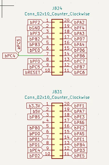
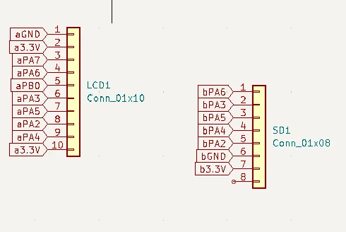
Some of these schematic parts are not included with KiCad. I luckily didn’t get a virus when procuring them.
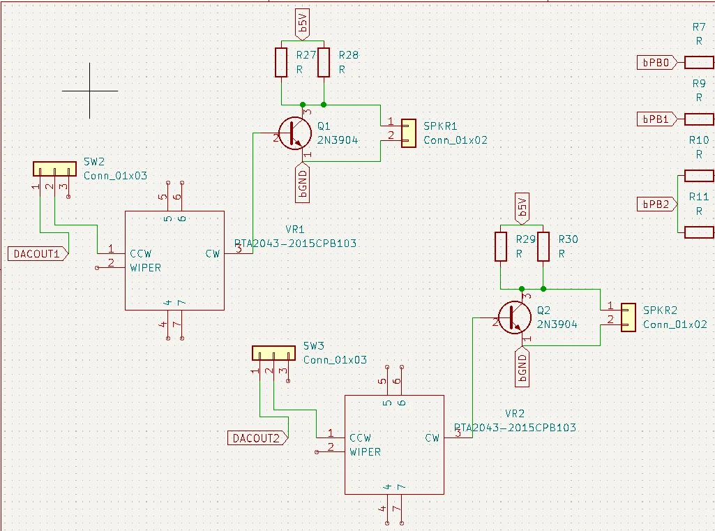

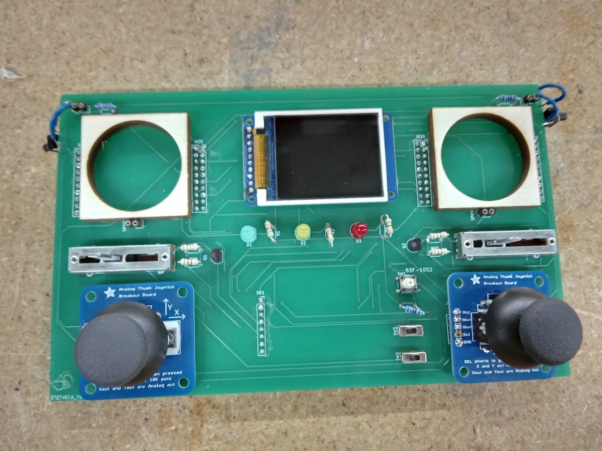
From left to right, top to bottom, these are
- The speaker + amplifier (DO NOT USE THIS CIRCUIT)
- The DACs
- One of the TM4Cs
- LCD and SD card
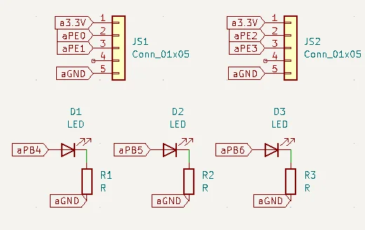
- Joystick and LEDs
- The other TM4C
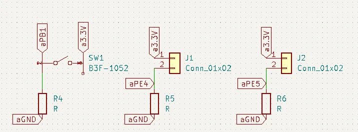
- Pause switch and trigger
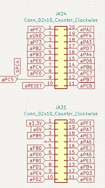
One thing is a lot of headers were used. This is good in a way because it allows switching out components and a ‘safe point’ for things that weren’t planned yet. It’s bad in a way because you already have the pcb, so you shouldn’t need to have headers.
These headers were also “round” headers. They only work with the “round” wires, not the “square” wires. However, a stripped jumper cable fits into the headers perfectly, leading to a very funny looking joystick and SD card after the solder.
Layout
This process is pretty annoying. They’ll make AI automate it eventually, it’ll because of designs like mine. So many right angles, traces are so close to each other, there are so many vias. ☠️
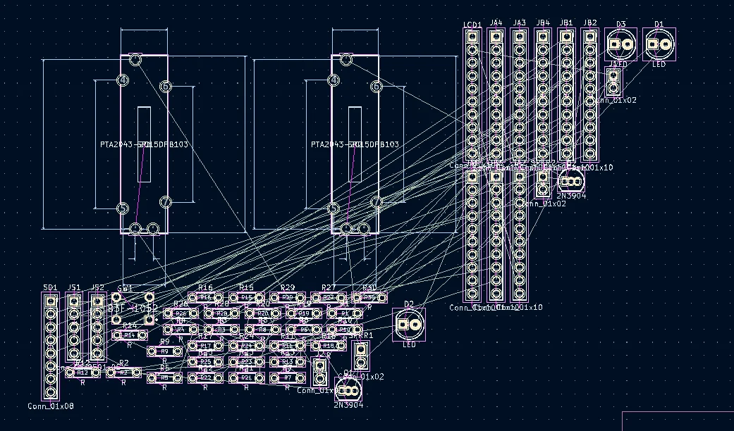
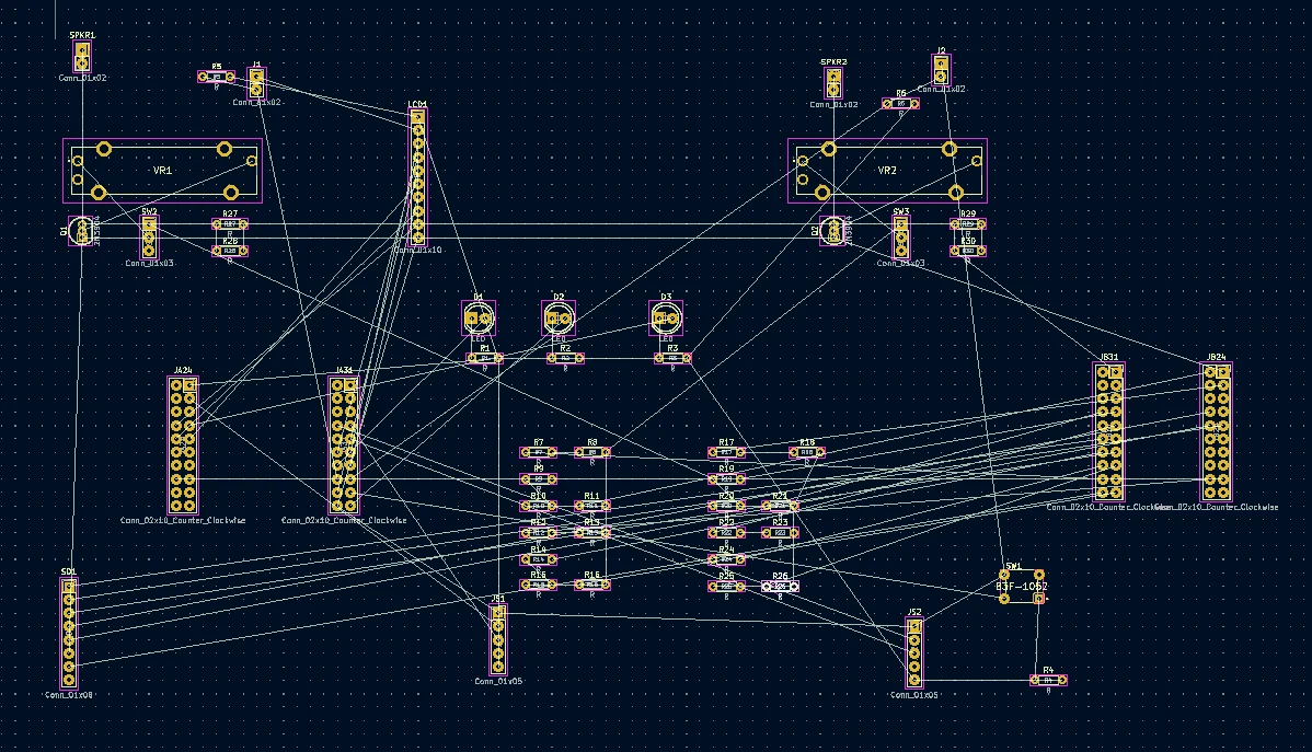
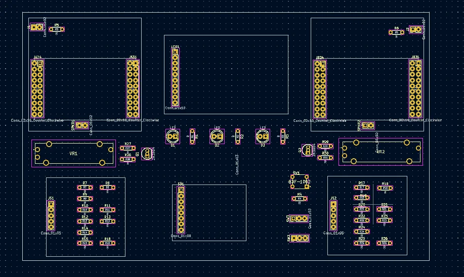
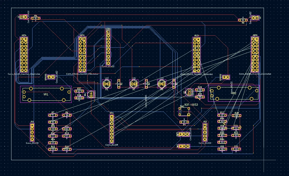
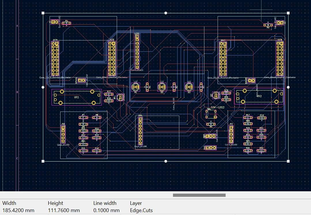
This is basically just a few pictures taken while working on it, I’m not even sure if the last picture is the final version.
Manufacturing
I used JLCPCB, because it was cheaper than PCBWay and I didn’t really trust other websites I saw (I really didn’t trust either of these two but you gotta do what you gotta do). They actually made it pretty fast, I think it took a week. The only downside the minimum PCBs you have to make is 5, and you have to pay for all 5 even if you’re only using one. So now I just have 4 extra PCBs…
Soldering
This was just pain. Brutal. Took forever. Accidentally soldered stuff on the wrong side of the board a few times. The most important lesson I learned was the solder gun is very good at cleaning up excess solder, while the wick is great for completely getting rid of solder.
I had to completely remove a component. Here’s the process for that. You first use flush cutters to cut off the excess wire. Then you put the wick on top of the solder/wire, and place the soldering iron on top of that. There will be some kind of “smoke,” just keep the soldering iron there until that “smoke” starts disappearing. You may need to do it on both sides. Afterwards, your through-hole should be looking, and working, as good as new.
Fixing Things
Quick pro tip, you will probably never have 2 or more seperate grounds. That defeats the purpose of the grounds, they will all be common. To fix these we had to use jumper cables. Apparently these are called blue wires, and coincidentially our jumper cables were blue.
Our slidepot is actually wired incorrectly. It’s wired to the entire resistance, really it should just be one edge and the wiper (the variable part of the resistance). This is fixed by shorting one of the ends with the wiper using more jumper cables.
The SD card (the standalone one for the music) is actually upside down, there wasn’t a way to fix this :(.
The triggers are very strange. I actually had a pretty good version where you have the 2 pins of the button attached to jumper cables to fit in the header, and the other two pins were hot glued onto the bottom of the PCB. Unfortunately, I soldered the wrong pair of pins (they were electrically connected already ._.), and the next time I soldered the buttons I did it worse and there was no more hot glue. The right button actually fell off and was never used (although it was supposed to be used for shooting).
So eventually there was a problem with the board not providing power from the TM4C to its components. This was checked by using the continutiy mode on a multimeter. Also fun digression. I had the tail end of the multimeter’s arrow pointing at the mode I wanted, meaning it was not on the mode I wanted it to be. I then heard and barely saw a spark, and began to lose my mind (luckily, this only blew out the red LED on my board, which wasn’t going to be used). Anyways, there was a clump of solder on the power pin, and this was bad. Very bad. By clump I mean it looks like there is a metal ball on the pin, there should be minimal solder. Luckily the solder gun fixed this issue and everything was back to normal.