This will probably be the most viewed post of the breakdown (if there’s even anyone who reads this). Let’s hop right in.
I will be discussing the implementation more than an overview of how raycasting works, but I will link the same references I used. In a very brief description, you have a field of view (FOV, it’s an angle), and you divide that up by some arbitrary number. For each of these FOV chunks, you trace a ray from the player to a wall, calculate the distance, and then draw a vertical column on the screen based on where the ray hit. Note that arbitrary number is going to be how many x pixels are on the screen, so it matches up nicely (if you change it you can get less or more detail). Anyways, there is a lot, this is gonna be a long post (code included!).
First Iteration
First, I basically copied some code from this guy but I had to convert all the floating point math to fixed point. Now the floating point stuff will have to be explained.
Fixed Point
There are going to be two important uses of fractions. Angles and distances. Angles need to be fractions because they will be in radians, which only goes up to 2 * pi (6.28). Actual radians can be below 0 and above 2pi, but that doesn’t really matter to us because we will just be feeding in angles to trig functions. The trig function will give the same result no matter how many extra 2pis you add or remove. The distances are fractions as a convenience so the result of the trig functions can readily be used. They didn’t have to be fractions.
I won’t go in depth on standalone floating point, let me just tell one case of how wrap-arounds are abused. You know how in a circle every +2pi is effectively the same? well, if we use the fixed point so that all ones is almost 2pi. When we add one, it will be 0, or 2pi.
Trigonometry
Initially to save ROM I wanted to actually calculate trig functions. You can do this with a taylor series
polynomial. The problem was I didn’t really want to spend the time optimizing and converting a taylor series
into code, and it didn’t have good accuracy over the range I desired. Trig functions are implemented with
lookup tables. So there is an array of outputs, and the outputs are mapped to the inputs. For example if I did
sin_table[3.14], I should get 0.
Some more details need to be ironed out. The angles use 16 bit integers. The entire part is fractional relative to 2pi. 0 will be 0 radians, and 2^16 will be 2pi (you can’t actually use 2^16, so 2^16 - 1 will be very close to 2pi). 2^15 will be pi, and 2^14 will be pi/2. That covers the input, the output will be “distances.” Really they are fractions so you can make them relative to anything, but making them fractions of distances is the most useful because that’s what these fractions will be used for (also note all regular trig functions take a length ratio and return an angle). Distances are 16 bit integers with the higher 8 bits being the integer part and the lower integer part being the fraction. You could say the number we put in the variable is x * 2^-8, so there is an implied “* 2^-8” on every distance. You will also need the inverse tangent, or arctangent, to draw enemies. Arctangent will take an angle (x / 2^16 * 2pi) and give a side length ratio, or just the opposite side if you assume the adjacent side is 1.
If you thought those were all the details, you would be wrong. There’s more! So there’s actually sin, cos, sec, csc, tan, cot, atan. If you start doing some math, you’ll realize you probably won’t have enough ROM for all of these functions (you only get 256 kB of ROM). Or maybe you do but you won’t have room for images, I never calculated it. Symmetry is exploited heavily. This is one of the highlights of my implementation that I didn’t really see anywhere else. So you look at the standard C library math functions. They work great for math and have a lot of stuff “built in,” and this is because of the math itself. You can throw in basically any number as the input in radians, and you’ll get positive and negative signs. I removed most of this “built in” functionality of math itself.
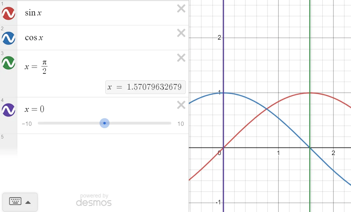
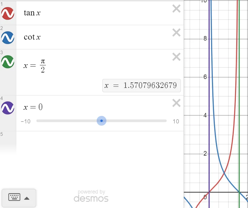
All the numbers used in the raycasting calculations are positive. Kind of like a vector, I used a magnitude and direction, but I made them seperate variables. You start with your input theta, and make sure it is less than pi/2 (represented as 2^14). If your input theta is greater than pi/2, you just subtract pi/2 from it, and every time you subtract pi/2 you add one to a “quadrant” variable. The quadrant variable will tell you the direction, the trig function will just give you the magnitude. This is because all the trig functions are symmetrical in a way that you only need to use the values from 0 to pi/2, everything else is just a reflection across the x axis, y axis, or both the x and y axes. There’s even more symmetry to exploit. All the “co” functions are their non-co counterparts going backwards. To understand what I mean, look at sin and cos. Sin(pi/2) = 1, cos(pi/2) = 0, sin(0) = 0, cos(0) = 1. If you remember your unit circle, if you look at sin(pi/3) and cos(pi/3), the x and y of the points in the circle are just flipped. A much simpler way of looking at this is the cos function is just the sin function shifted to the right by pi/2, but the shift explanation doesn’t work for explaining the other functions.
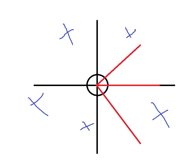
Here are some pictures showing the symmetry:

Here is the function that “normalizes” thetas and gives you a quadrant.
uint8_t mm_convert_theta(uint16_t *theta)
{
	uint8_t data;

	/* Convert theta */
  data = 0;
  while (*theta > 0x4000) {
		*theta -= 0x4000;
		++data;
  }
  if (data & 0x1) *theta = 16384 - *theta; /* Make sure theta is based off x-axis and not y */
  if (data > 1) data ^= 0x1; /* Convert quadrant to format specified above */

	return data;
}
The format specified above was specified before this code became its own function. So you use the lowest 2 bits
in data. The lower bit is x and the higher bit is y. If the bit is one, it’s negative, and if it’s 0 it’s
positive. It’s a little funky but it made it easier for me when I started traversing the rays. That first if
statement is worth explaining. It will branch on quadrants 2 and 4, and a visual will help explain this.
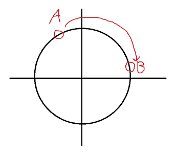
The sine of A and B should be the same, but they are clearly not in the picture above. This conversion will solve this problem.
That pretty much sums up all of the trigonometry. All the math related code can be found here
The tables were generated with a python script, which is left as an exercise to the reader to decode.
Problems
The tutorial is great but it relies on floating point math. Eventually for rendering objects, you needed to calculate an inverse (1/x type behavior). Divisions are slow and I wanted to avoid dealing with this math. It also was based of matrices and vectors, which makes total sense in terms of 3D computer graphics, but it was a bit overkill for this and I didn’t want to think about or do the work to convert all that matrix stuff into fixed point. Originally I liked this method because I saw another method where every ray is cast twice, for the x and y direction, and then you use the shorter ray. With Lode’s method, you only need to shoot a ray once.
There was also a visual error with my implementation, maybe you can tell what it is. The good part about the raycasting good is I somewhat modularized it into different calculations, so some of the lower level draw functions were working perfectly fine, it was just the calculations of the previous steps were wrong.
Second Iteration
Now I am following the guide from this guy. This does use the x and y casting for each ray (the double cast thing I was talking about), but if I remember correctly actually simplifies some parts of the fractional wall detection compare to Lode’s method (there ends up being a calculation you don’t need to calculate anymore). This guide provides a lot of math and some logic, but no code. This actually turned out to be beneficial, because I really had to understand what was happening, no more just converting code.
First I’ll explain the map and then basically walk through the code.
The Map
If we want to draw a map, first we need a map. I’ll leave the enemy part to a later section, as we can seperate how the world rendering and enemy rendering work.
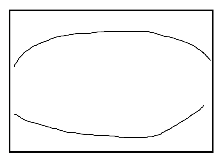
A map looks just like this:
const uint8_t circle[] = {
 1, 1, 1, 1, 1, 1, 1, 1, 1, 1, 1, 1, 1, 1, 1, 1,
 1, 1, 1, 1, 1, 1, 1, 1, 1, 1, 1, 1, 1, 1, 1, 1,
 1, 1, 1, 1, 1, 0, 0, 0, 0, 0, 0, 1, 1, 1, 1, 1,
 1, 1, 1, 1, 0, 0, 0, 0, 0, 0, 0, 0, 1, 1, 1, 1,
 1, 1, 1, 0, 0, 0, 0, 0, 0, 0, 0, 0, 0, 1, 1, 1,
 1, 1, 0, 0, 0, 0, 0, 0, 0, 0, 0, 0, 0, 0, 1, 1,
 1, 1, 0, 0, 0, 0, 0, 0, 0, 0, 0, 0, 0, 0, 1, 1,
 1, 1, 0, 0, 0, 0, 0, 0, 0, 0, 0, 0, 0, 0, 1, 1,
 1, 1, 0, 0, 0, 0, 0, 0, 0, 0, 0, 0, 0, 0, 1, 1,
 1, 1, 0, 0, 0, 0, 0, 0, 0, 0, 0, 0, 0, 0, 1, 1,
 1, 1, 0, 0, 0, 0, 0, 0, 0, 0, 0, 0, 0, 0, 1, 1,
 1, 1, 1, 0, 0, 0, 0, 0, 0, 0, 0, 0, 0, 1, 1, 1,
 1, 1, 1, 1, 0, 0, 0, 0, 0, 0, 0, 0, 1, 1, 1, 1,
 1, 1, 1, 1, 1, 0, 0, 0, 0, 0, 0, 1, 1, 1, 1, 1,
 1, 1, 1, 1, 1, 1, 1, 1, 1, 1, 1, 1, 1, 1, 1, 1,
 1, 1, 1, 1, 1, 1, 1, 1, 1, 1, 1, 1, 1, 1, 1, 1,
};
It’s just an array of tile ids. 0 is used for no walls, while numbers will indicate which texture to use. Positions of “things” in the world (player, enemies, bullets) are represented as those “distances” from the fixed point section. A 16 bit integer with 8 bits of integer and 8 bits of “fraction.” The integer tells you which tile you are on, so you can go from 0 - 256 (I don’t remember if there was some other restriction preventing us from making a map that was 256x256, it could work but it would be pretty big, 16x16 was already a decent size). The fractional part tells you what fraction of the tile you’re on. If you’re 0x??80, 0x??80, you would be right in the middle of the (??, ??) tile. Now comes the fun part: raycasting. I’ll go in reverse order of how the functions are called.
Draw world strip
This function draws one vertical line. One thing I should point out is there is a lot of flipping of WIN_W and WIN_H (window width and height), because we still use the LCD in ‘portrait’ mode, but we physically rotate it to get ‘landscape’ mode. There is a way in the LCD setup to just use a ‘landscape’ mode by default, but we just added a lot of work (it was also because of scanlines, althought based on how our LCD works I don’t think it really makes a difference, it may improve the performance of some LCDs though).
Starting with the parameters, screen x is the x position on the screen to draw the vertical line (so it’s actually a y coordinate but forget about how the screen is rotated for a bit). The distance is how far the tile is, which is important for determining its height. Data has the tile offset in the lower byte. Tile is the id of the tile hit, the exact same number on the map.
The real meat of this function is texture drawing, and texture scaling. It’s actually really simple. So for starters, textures are as an array of color indices (see the display blog post to know why) and they are all 64x64. At some distance, the height will be 64. At another, further, distance, the height will be 32. At another, closer, distance the height will be 128 (this is also the max height of the screen). Let’s start by drawing the image at its normal height, 64 pixels. We need to first find the row in the image we want to draw (in hindsight this makes stuff more confusing, all the images are rotated 90 degrees but having a little different code here would prevent the need for that. If you have a non-rotated image, you are looking for the vertical column to draw, but since it’s rotated we need the horizontal row, because that becomes the vertical column). The lower byte of data has this information. the fractional part of data has a range of 256, if we divide this by 2, (» 2 in the code), the range of data is now 64, which perfectly aligns with the texture size. Isn’t that wild! Note that bitshifting 2 removes the 2 most precise bits of the fraction, that’s perfectly okay for this case. Now we know which row to pick from the texture, so we just go down on the screen and draw every pixel. Now what happens if we get a height of 128? To make the image appear bigger, we can just draw every pixel from the texture twice. It works out! Maybe you can guess how we make the image smaller? Instead of repeating pixels (or I guess they are called texels), we skip them.
This is great news, but what about distances in between of these perfect cases? There is another table which
converts a distance into a tex_step, this is the “step” of a texture, and it is an 8:8 integer (this
is how I like to represent a 16 (8 + 8) bit integer with 8 integer bits and 8 fractional bits in fixed point).
For a height of 128, our tex_step is 1/2, and for a height of 64, our text_step is 2. This isn’t really fancy
image interpolation, it’s really simple. There is some math to figure out start_y which accounts for height to
center the tile on the y axis, but I won’t explain that.
There is also a z buffer being set. Keep this in the back of you mind because it will become important later for drawing enemies.
Also you may be wondering why do we need to just draw one vertical line and not the whole tile. It’s possible for one tile to have different height, see the image below.
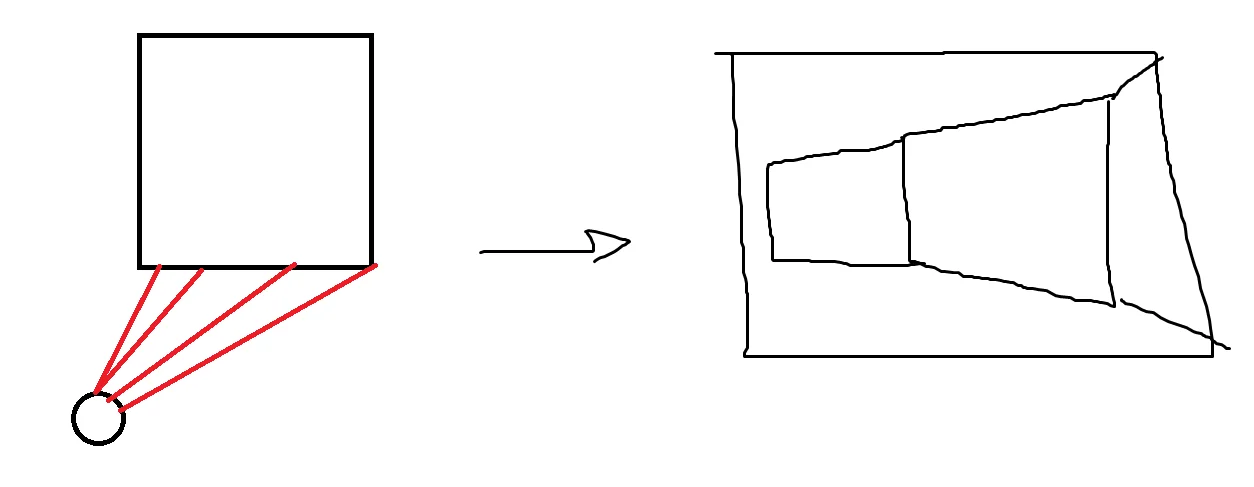
Also each ray is corresponding to one x coordinate, so it just works out this way.
Draw world ray
Luckily the parameters are documented well enough this time.
First I need to explain what ri and rj are.
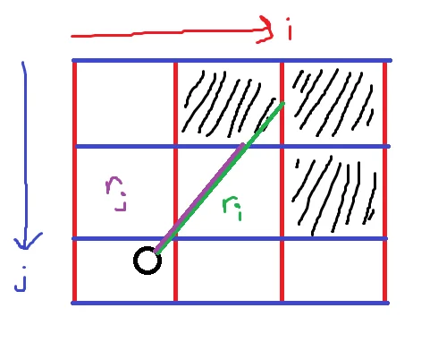
i goes in the x direction, and represents the vertical parts of the walls.
j goes in the y direction, and represents the horizontal parts of the walls.
ri is the distance to the vertical wall, and rj is the distance to the horizontal wall.
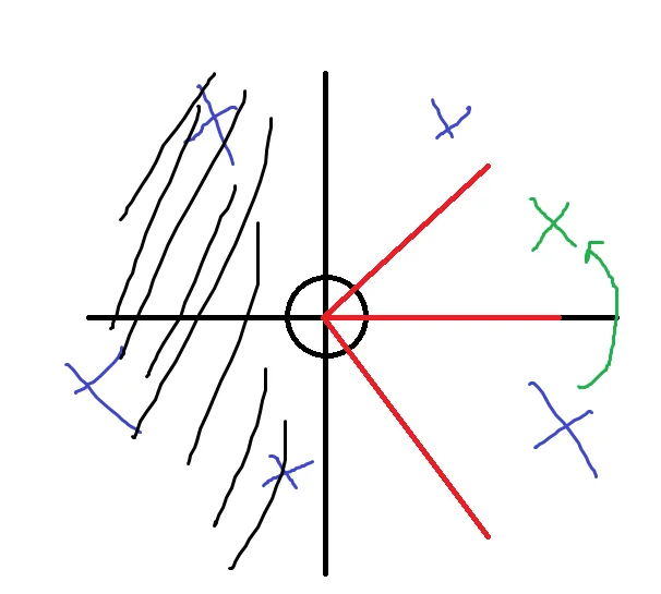
The next section talks about finding ri and rj, but once found you take the smaller one and that’s the distance to the wall. There is just one more important thing this function does and it’s correcting the distance. See the following visual.
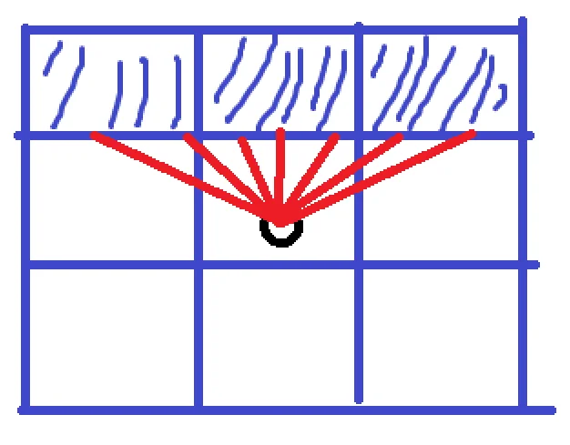
This fisheye effect occurs because the outer angles have a further distance than the inner angles. When we look at a wall, this doesn’t happen, and this effect just looks weird. It turns out you just fix this by multiplying the distance with the cosine of the difference of the the ray angle and player angle.
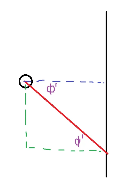
Cosine is adjacent over hypotenuse. Adjacent is the corrected distance, and the hypotenuse is the wrong distance, so it works out. It’s easy to see why this works when you are looking exactly up, down, left, or right. I haven’t really thought about how exactly it works when you are in between, but hey, it works (you know it works if it looks good, the math is just math after all).
Now all you need to do is find ri and rj.
Find ri
This is the most ‘raycasting’ part of the raycast. It’s where you actually traverse the ray through the world.
Math revisited
This function does a lot, first I will explain the bitshifting going on. There are two cases that appear in this code: one where you will need to bitshift 16, and one where you will need to bitshift 8. Before even talking about either case, what is up with this ‘strange’ multiplication? It has to do with the precision of fixed point.
Let’s begin with multiplying two distances together. Remembering how the 8:8 integers work, we get this
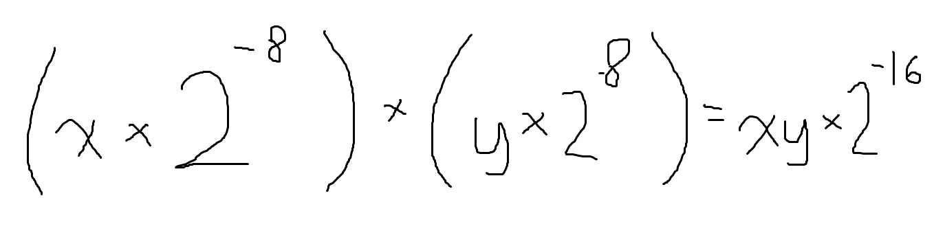
You may be able to figure out why a shift 8 is needed, but first I should talk about the cast to a uint32. A uint16 x uint16 cannot be stored in a uint16 without losing information, it basically makes the multiplication useless. If we look at 8 bits, we have a range of [0, 256) (The range goes to 0-255, I think writing it like this will make what I’m about to explain a bit easier to understand). If we square the range we get [0, 65,536). If you’re fancy with your powers of 2 you intrinsicly know that’s 2^16, you need 16 bits to store that.
Here’s the extra information you can skip if you want. If we take 255 and square that, we get 65025. You will still need 16 bits to represent this number, so that’s why I just used 256, it makes it easier to see how many bits you need.
For every x bits we multiply, we will need 2x bits to store it. We have two groups of 8 (16) so we need 32 bits to store everything. Now we just need to convert this number back into the 8:8 format. I remember earlier I mentioned I didn’t know the limitation of the map size, it will boil down to what happens here. Bitshifting 8 will chop off the 8 lowest bits. Another way to see it is it will multiply by 2^8, which turns that 2^-16 in the picture to a 2^-8. The less significant the fraction bit it, the more precise it is. I used some uneccesary wording but the important thing is it’s “less significant,” so we can cut it off. When we cast back to a uint16 (from a uint32 still), the upper 16 bits will be cut off. Since we already shifted everything to the right, it will effectively cut off the upper 8 bits of the integer part of the number. This means after multiplying, the maximum distance we can have is 2^8, or 255. So when you make your map, at no point should the player see a length of 255 (look diagonaly). Our maps were 16x16, which almost hits the limit but its really 14x14 because the outer walls of the map are all walls. This ‘clipping’ problem will actually not affect wall rendering, because at the max distance you won’t be able to see the wall anyways. It will probably cause problems with enemies and projectiles, so just be careful.
The bitshift right 8 is used a lot, So when is the bitshift right 16 used? So here’s where we talk about the math trig function again. I didn’t properly explain the outputs. For tan, cot, sec, and csc, they will return a 8:8 number. I noticed when using the 8:8 format for sin and cos, I got pretty bad results. This is because the range of these two functions is [0, 1). Eight bits will always be wasted, so we can edit this to make it a little more precise. The sine table actually stores 0:16 integers, they are 100% the fractional part of the integer. That means when we multiply a sin/cos output by a distance, it is like below:
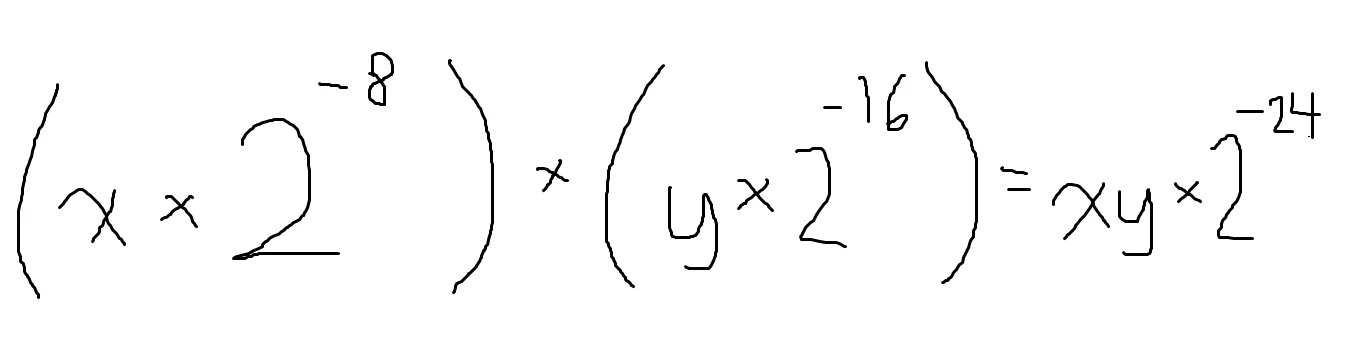
A bitshift of what number will get us the correct result? That’s right, 16. From what I’ve seen people struggle with fixed point, so maybe read this a few more times. Work out some problems. Take a break. There will be more math when getting to the enemies but not this detailed code/math logic.
Raycasting part
Because we will cast two seperate rays, there is a nice algorithm we can use. We will look at ri. Since we are looking for a vertical wall intersection, we can always move on the x-axis by one or negative one. I think this is called “Digital Differential Analysis,” (DDA). I think the guides explain it well so I won’t go too in depth. First we need to find the nearest intersection (this is the first step), and then we just step until we hit a wall. It’s really simple, you just need to work out the trig functions to make sure you’re getting the correct lengths. There are only two more things I would note here. One is now you can see how the quadrant system and ‘magnitude’ and ‘quadrant’ form of distances I mentioned earlier works. The other is the tile offset is found here, and its a pointer so we can use it as another output.
rj
rj is found the same way, you just need to change some trig functions and swap some xs and ys.
Draw world
Now that the hard work is done, we hit the easiest function. This just casts multiple rays based on the player’s angle, which is noted as phi. Phi is kept in the middle of all the rays cast.
Enemies
Compared to raycasting scenery, there are very few guides on how to raycast enemies. However, we needed them for our game, so I had to go DIY (or really DIM). What I read used lists and other data structures to sort all the enemies and then do some things, but this really wasn’t necessecary since there weren’t that many enemies in a level.
In a broad sense, to draw enemies you need to use a ‘reverse raycast.’ Instead of shooting rays to unknown positions, you know the position of the enemy so you just calculate its distance to the player. Oh boy, if only “you just calculate its distance to the player” was as easy as it sounds. Its not.
Look at this scene:
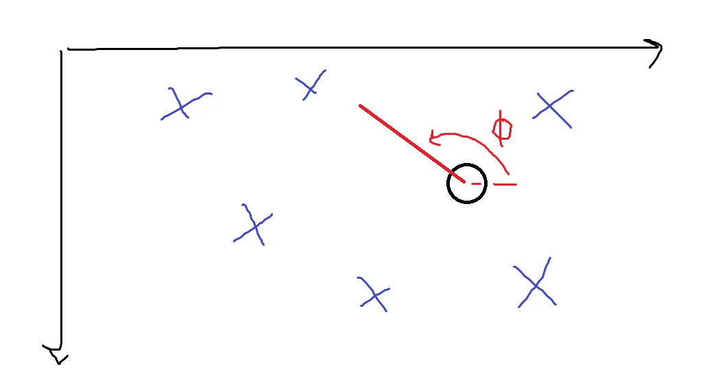
Where would you even begin trying this? However, this is where I pulled out the “high IQ” move of just making it simplier. Try this scene.
There is so much simplification we can do. Removing all the enemies to the left of the player is easy, we just don’t draw them. There’s another trick we do which will help us out.
In this form, it’s very easy to figure out what to draw. We will look at the enemy’s position to know if it’s in the “view” or not. The hard part is applying transforms to put everything into this simple form. Also, the flip over the x-axis allows the continued trend of all positive values. They actually need to be positive because distances are unsinged.
Applying a rotation
While I could derive everything else so far, I could not derive rotation around a point. My geometry skills were (and at the time of writing, are) not of that caliber. Luckily google exists, I found a formula which uses some matrix stuff. I converted the matrix stuff to stuff I could use and it works.
I think This guide pretty good, I think I ended up just finding an image with the formula and using that though.
The rotation code is contained within its own rotate function.
It looks complicated but that’s just because of the need to always keep track of the sign while always using positive numbers. Remember, all numbers are positive, you need another variable to know their sign.
Drawing an enemy
After you rotate an enemy, you find theta. Theta is the angle that the player would normally send out as a ray, but the important thing is this is where the enemy’s x position will be. Then the distance is calculated, and this will determine the height of the enemy, just like it determines height for walls.
The draw code is almost the same as the world/walls. The difference is an enemy x’s could be out of the FOV, but that is one point of the enemy, the center. The edge of the enemy could still appear on the screen. This is why there is a draw strip’s’ function. We try to draw all the strips, knowing that in this edge case maybe all the strips won’t be drawn. This could also try and draw an enemy that isn’t visible at all, but since there aren’t that many enemies, this is okay.
One last thing which is unique from drawing walls is the z-buffer. When we calculate the wall distances, we had to store the distances in this z-buffer. This is the wish.com version of a z-buffer in something like OpenGL, because it stores the distance for the entire vertical column, not every pixel. This leads to a weird display problem were the transparent part of an enemy/bullet can cover up something behind it. First, to draw an enemy, its distance must be less than what’s already in the z-buffer, and then you update the z-buffer so you don’t have weird problems when two enemies are in roughly the same position. You can solve this problem by have a packed table of 128*160 bits (not bytes) of a transparency flag, where you ignore the z-buffer if that pixel is transparent. We couldn’t implement this because we ran out of ROM. How? Well, the code needs to be stored somewhere, it’s stored in ROM. We used so much that we couldn’t even write an if statement to give the final boss some interesting attack patterns. You also need to have enough RAM, but since we were already out of ROM I didn’t bother calculating how much RAM it would take.
And there you have it, what was for me the hardest part of all this code. I skipped over talking about that x-axis flipping of enemies because I think it would make my head hurt trying to remember what that part of the code does. There is just a lot of keeping track of the sign of things because I only used positive, unsigned numbers.
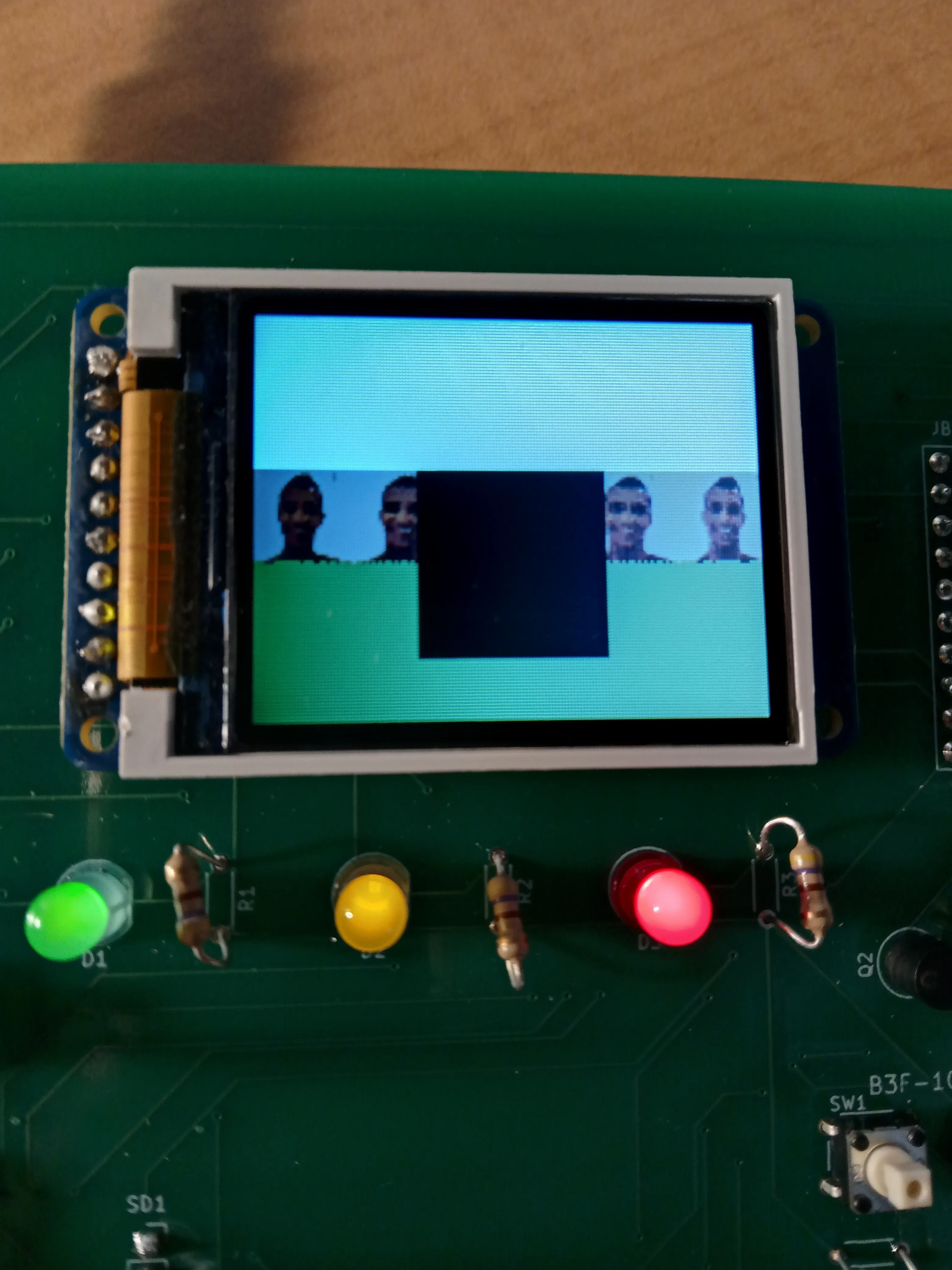
I started simple with the enemies. At first they were just black squares.
Combat
I am not going to discuss the combat in great detail, it is really not at all complicated. There is just a lot of code, but if you understand everything up to drawing enemies, this is really a walk in the park. The bullets are just sprites. All collision detection is AABB.
Debugging
With the LCD I could only see the output, and to really fix some of the visual bugs I needed to see what was going on. So I copied all the code, dropped it in visual studio, and used SDL to make a debug thingy. The great part was I only needed to change code for inputs (player control) and outputs (the screen). If you see a comment saying “injected code,” it is there just to get more debugging for the visual studio “version.” I won’t be explaining how it works, but as usual the code will be available if you want to take a look. Modular design is super important when you code, this could be an example of why.
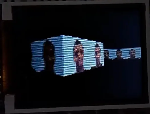
Here are some pictures of the debugger while running.
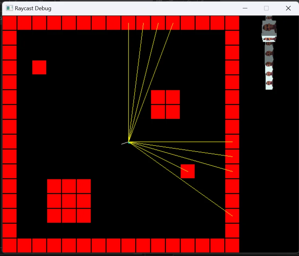
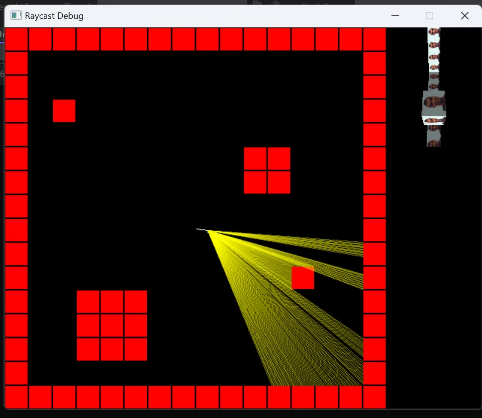
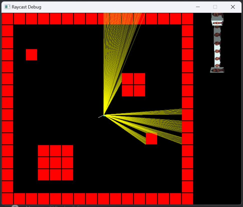

This debug project doesn’t have enemies, I yolo’ed that directly on the embedded system code. By the way, we are using Keil as our IDE. However, there are still problems with the raycasting! Sometimes a random strip is drawn, so maybe you can fix it! Aren’t exercises left to the reader fun?
Other Remarks
This took some time to think through. A lot of head hurting moments. Overall it was pretty cool.
The key thing to the math and stuff is always use positive numbers and note the reduced domain of the trig functions.
Here are some glitches.
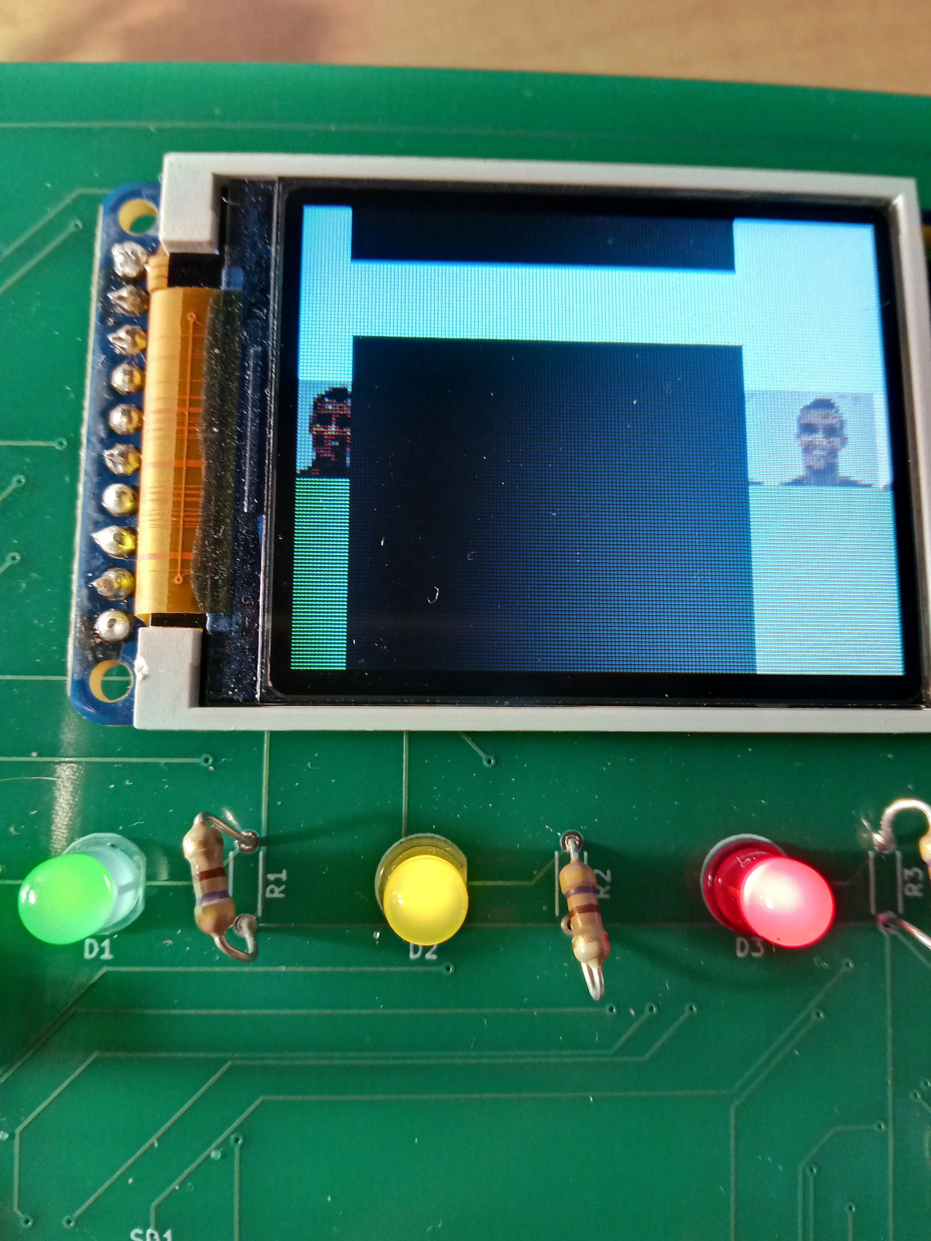
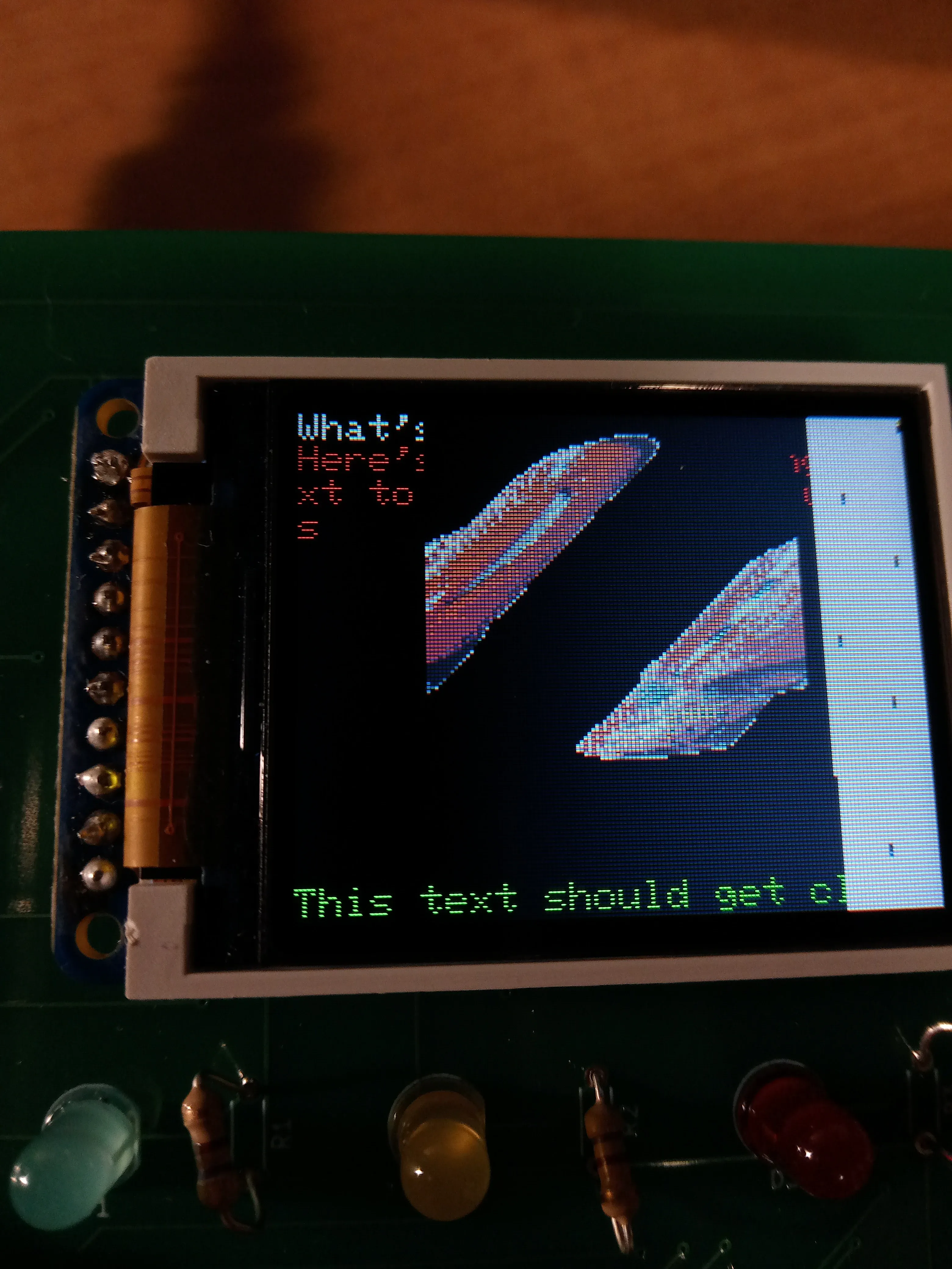
Finally, here is one scene from the game