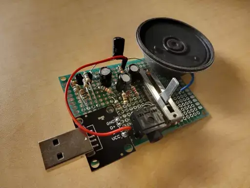
This is how to not make an audio amplifier.
The first thing I guess is the speaker is 8 ohm and rated for 0.5 watts. I was making a simple two stage bjt amplifier comprised of a common emitter stage and an emitter follower stage. The common emitter is supposed to provide the power gain, and I think of it as a voltage amplifier in this scenario because that’s the input to the emitter follower. The follower is needed to be a buffer because 8 ohms is a very low resistance and connecting it directly to the output of the common emitter will mess things up. For power it is using USB.
I spent a week in LTSpice trying to find the right values for everything and trying out different circuits until I finally ended up with this.
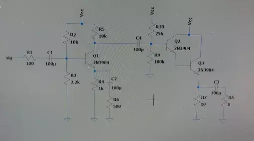
At least I think, the final version may have been a little different from this.
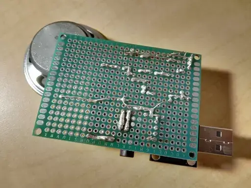
One fatal mistake I made was directly soldering this onto a perfboard, instead of testing this out on a breadboard. I was also using a perfboard for the first time so I didn’t really know how it worked, lol. Now I think I know how to use it better. At the end of soldering, the bottom of the audio amp looked like this:
So I plugged it into my computer, connected my aux to aux cable, and was met with disappointment. It didn’t work. Actually one of the transistors started heating up way too much so I had to disconnect everything quickly before something exploded (unlikely). I then started probing things with my multimeter, and nothing matched the simulation. I took out the audio signal and just tested DC bias conditions and all of those were wrong. Either my LTSpice models were just bad, or maybe LTSpice didn’t take into account the impedances of the transistors combined with their connected resistors. I did some surgery and flipped some resistors around, swapped some, and got better bias values, but the amplification was still pretty bad.
I think the main take away from this failed project is to actually test stuff out in the lab, and don’t rely on the simulation. Or maybe just find better simulation software.
I am definitely working on improving this and my goal is to make a working audio amplifier sometime soon. A lack of information really helps, but I will start figuring things out. I still don’t understand how the audio signal itself works, for example is it pure AC or does it have a DC offset, and what are the range of values it can take? I can probably just test this out in the lab, but a quick Google search didn’t give me a concrete answer. I found a book on audio amplifier design as well and it’s more involved than I thought. I will basically be making an op-amp, but I think I will.
I tried incrementally building the original circuit on a breadboard, but the audio quality is pretty bad. It could actually amplify a 1 kHz pure sine wave pretty well, but it was weird when I increased the volume. The pitch changed, because that makes sense. Here is Stickerbush symphony with very low quality.